
What is the power factor: –
The ratio between the active power and the apparent power cos Ǿ is known as the power factor.
The line current drawn by induction motors consists of two components, Magnetizing current and Power-producing current.
The magnetizing current is the current which is required to produce the magnetic flux, and this component is lagging the voltage vector by 90 Deg (Lagging because vector rotation is anticlockwise)
The power-producing current is the current which reacts with the magnetic flux to produce the machine’s output torque of the motor, and this component is in the time phase with the voltage. This means that the phase of the motor current (vector sum of the magnetizing and power-producing current) will be displaced about the network voltage by the angle Ǿ
Why raise the power factor? –
A motor running under no-load consumes almost only reactive power.
Active power: The power consumed in an AC circuit is called active power. Active power is the power that continuously flows from source to load in an electric circuit.
Reactive power: Reactive power is the power that continuously flows from source to load and returns to the source in an electric circuit.
Plants containing many motors consume a considerable amount of reactive power. If the machines run at no load for a more extended period. In that case, the reactive power requirements will also be large compared with the need for active power, and the power factor can become very low, affecting the power tariffs. In this condition, it is a must to correct the power factor.
By improving the power factor, we can achieve extensive savings.
The total apparent power of the utility power will reduce, reducing the generating losses throughout the complete supply and distribution system.
A higher power factor reduces the load on transformers and distribution equipment.
The losses in transformers and distribution cables are proportional to the square of the line current. So, a high-power factor will result in a direct saving of electric power.
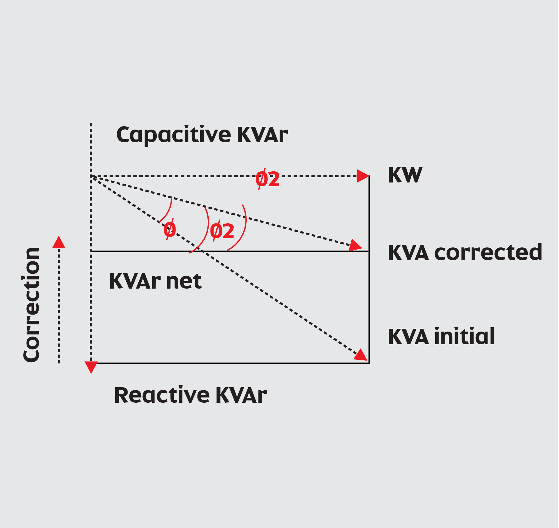
How to improve the power factor: –
The reactive power component (KVAr) must be reduced to improve the power factor for a given load. This component of reactive power lags the power component by 90 Deg. So, one way to reduce the effect of this component is by introducing a reactive power component that leads the power component by 90 deg. This can be accomplished by using a power capacitor, as shown in the power diagram resulting in a net decrease of the angle Ǿ=Ǿ1-Ǿ2 of an increase in the power factor.
The amount and location of the corrective capacitors must be determined from a study of the distribution system and the source of the low-power factor loads.
Where to locate capacitors:
The power factor correction capacitors should be connected as close to the low-power factor load as possible to reduce the system losses.
In some cases, the capacitors can be located at a specific power feeder.
In other cases, with large motors, the capacitors will be connected as close to the motor terminals as possible.
The power factor capacitors are connected across the power line in parallel with the low-power factor load.
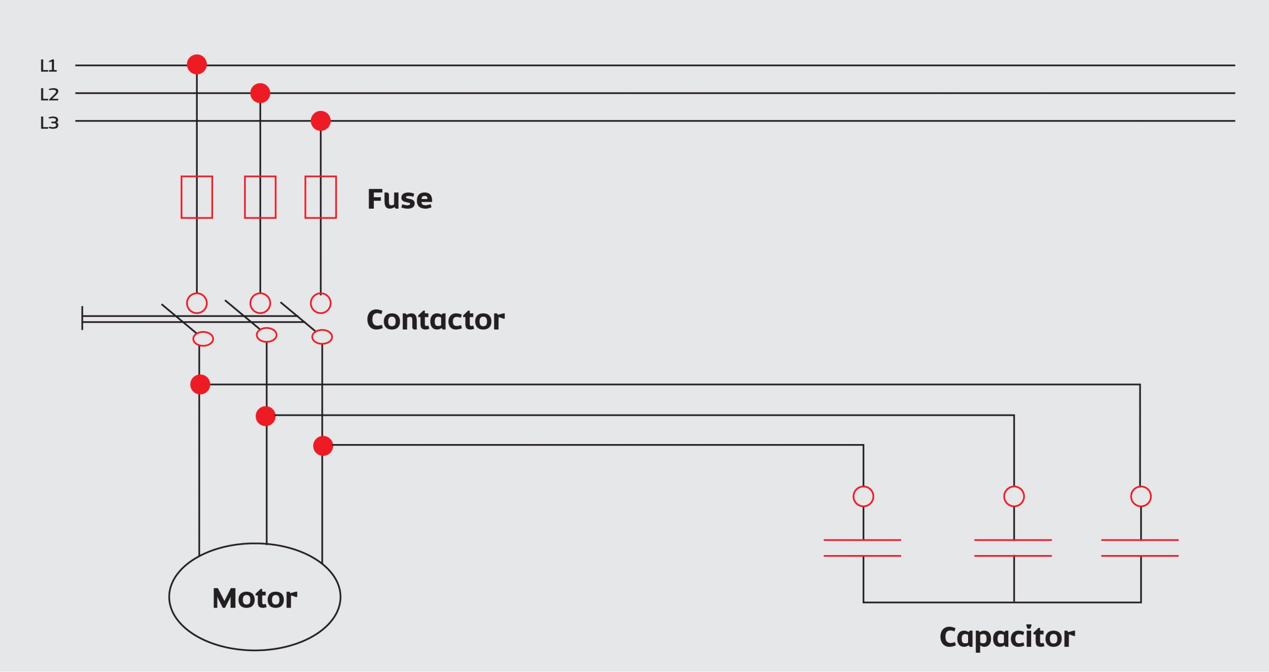
The circuit diagram, power capacitor connected to the motor terminals.
Connecting the power capacitors at the motor terminals and switching the capacitors with the motor load is a very effective method. No extra switch or protective devices are required and the line losses are reduced from the point of connection back to the power source. Corrective capacitance is supplied only when the motor is operating.
The following points have to be considered.
It is necessary to reduce the overload relay setting to maintain proper overload protection.
Never connect the capacitors directly to the motor when open transition starting is used such as star-delta and autotransformer.
In this case, self-excitation voltages or peak transient currents can cause damage to the capacitor and motor.
In these types of installations, the capacitors should be switched with a contactor interlocked with the motor starter
Size of the capacitor to be installed:
The size of the capacitor should not be too large if the power factor correction on the motor is directly applied. When the motor is disconnected from the supply, it runs as a generator as long as it rotates and the capacitor supplies the magnetizing current.
If the capacitor is too large, it will produce a higher magnetizing current than expected, generating a higher voltage than its rated voltage.
The selection of capacitors should be with a maximum rating corresponding to 90% of the no-load output of the machine.
Air compressors consume significant amounts of energy to supply power for industrial applications. If you consider all the costs of running capacity, you will realize that any savings therein will lead to a positive impact on your overall power cost management.
Contributor: ELGi
TO LEARN MORE, contact our IAS air specialists.